TCP/IP Five Layer Model
- Application Layer (Http…)
- Transport Layer (TCP, UDP)
- Network Layer (Wide Area Network)
- Data Link Layer (Local Area Network)
- Physical Layer (Cable, Fiber)
The Basics of Networking Devices
Cables
- Copper Cable
- Fiber
Hubs
Simple hub, data collisions might happen. Physical Layer Device.
Switch
Like hub, but no data collisions. Data Link Layer Device.
Router
Forward data between independent networks. Network Layer Device.
Border Gateway Protocol (BGP)
Router share data with each other via this protocol, which let them learn about the most optimal paths to forward traffic
The Physical Layer
Data transferred through copper cable by changing voltage of the electricity. Its called modulation, or line coding.
Twisted Cable
Full Duplex
Cables that support send & receive data at same time. Usually some wires are for send and some for receive.
Half Duplex
Cables that support send & receive data, but not at same time.
RJ45
Most commonly used copper cable. Yellow light for connectivity and green is speed indicator.
Ethernet Over Twisted Pair technologies
Use twisted-pair cables for physical layer of an Ethernet computer network.
Data Link Layer
MAC(Media Access Control) address
48bit length and every device has its unique MAC address.
CSMA/CD(Carrier Sense Multiple Access / Collision Detection)
When a collision is detected, the device will wait a random time and try send data again.
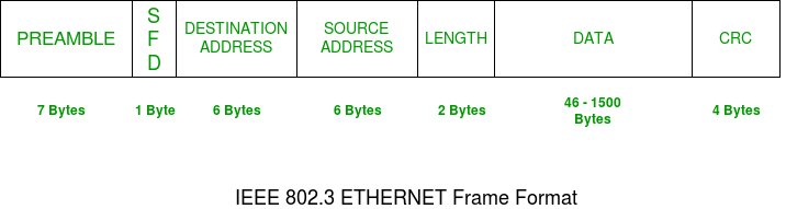
An Ethernet Frame
Ethernet (IEEE 802.3) Frame Format
Preamble
PRE (Preamble) indicates the receiver that frame is coming and allow the receiver to lock onto the data stream before the actual frame begins. But today’s high-speed Ethernet don’t need Preamble to protect the frame bits.
Start of frame delimiter (SFD)
This is a 1-Byte field which is always set to 10101011. SFD indicates that upcoming bits are starting of the frame, which is the destination address.
Destination Address
Receiver’s MAC address.
Source Address
Sender’s MAC address.
Data (Also known as Payload)
Both IP header and data will be inserted here if Internet Protocol is used over Ethernet. The maximum data present may be as long as 1500 Bytes. In case data length is less than minimum length i.e. 46 bytes, then padding 0’s is added to meet the minimum possible length.
Cyclic Redundancy Check (CRC)
CRC is 4 Byte field. This field contains a 32-bits hash code of data, which is generated over the Destination Address, Source Address, Length, and Data field. If the checksum computed by destination is not the same as sent checksum value, data received is corrupted.